Vapor and liquid load
Vapor flow, condensate rate, droplet size, foaming and startup surge establish vessel diameter and hold-up.

Collection and vacuum-system protection
A vacuum-rated receiver that collects liquid, manages carryover and provides stable separation between process equipment and the vacuum source.
Quick answer
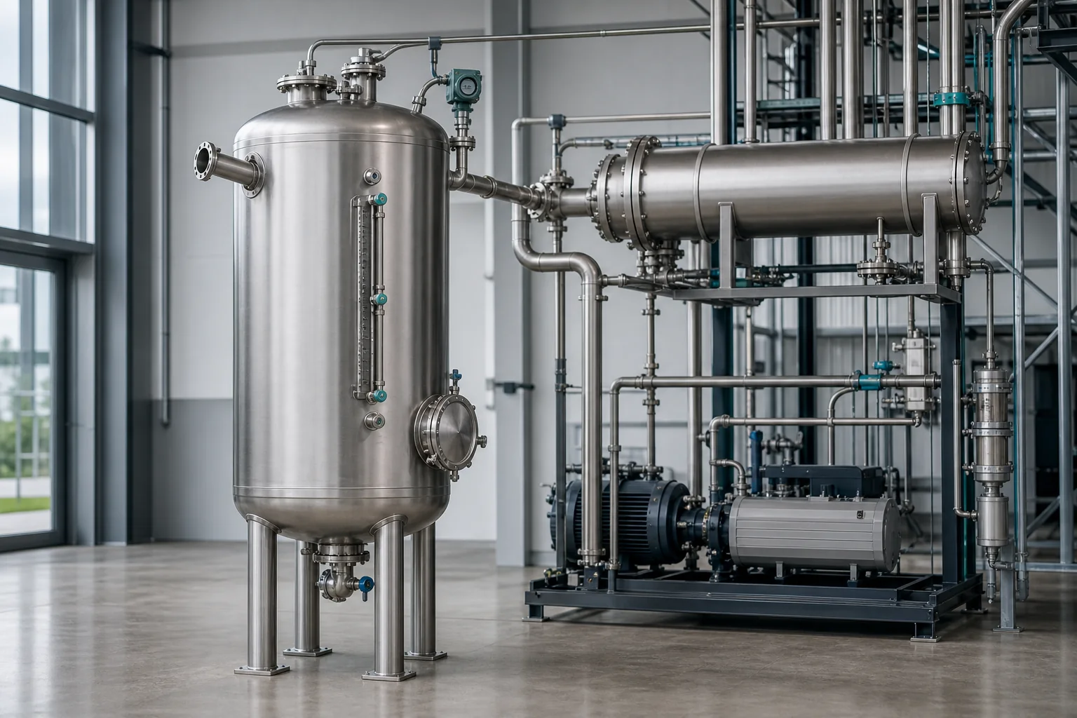
A vacuum receiver tank is installed between a process and the vacuum source to collect condensate or entrained liquid, provide temporary hold-up and reduce carryover into the pump. It is mechanically designed for the specified vacuum, temperature and credible pressure cases.
Receiver performance depends on vapor flow, droplet loading, condensate rate, residence time and liquid-control philosophy. Startup surges, foaming, cleaning liquid and a blocked outlet must also be considered.
Vessentra coordinates inlet momentum control, demisting, level range, drain or pump-out, condenser interface, vacuum connection and instrumentation.
Typical applications
Application details are reviewed before equipment configuration is finalised.
Engineering configuration
The equipment is developed from process inputs, operating conditions, cleaning requirements and site interfaces.
Vapor flow, condensate rate, droplet size, foaming and startup surge establish vessel diameter and hold-up.
Inlet orientation, momentum control and optional demister are selected to reduce liquid carryover at the design flow.
Sight indication, transmitters, alarms, drain valves or pump-out controls are arranged around usable collection volume.
Condenser, receiver, isolation, vacuum source and protection devices are coordinated as one operating system.
Specification guidance
Project limits are confirmed through engineering review. These fields describe the decisions needed for an accurate, application-specific configuration.
| Vacuum condition | Specified minimum absolute pressure or full-vacuum case |
|---|---|
| Vapor flow | Normal and peak load defined by process |
| Liquid hold-up | Sized for condensate rate and discharge strategy |
| Product-contact material | Stainless steel or compatible alloy |
| Internals | Inlet device and optional demister by separation duty |
| Level control | Local indication, transmitter, alarms or pump-out logic |
| Orientation | Vertical or horizontal by separation and layout |
| Cleaning | Drain, flush or CIP provisions to service requirements |
Common questions
It collects condensate or entrained liquid between the process and vacuum source, provides temporary hold-up and helps protect vacuum equipment.
Diameter and volume follow vapor flow, allowable velocity, separation target, condensate rate, surge allowance, usable level range and operating time.
It can be engineered for compatible solvents when materials, seals, static control, hazardous-area needs and vent handling are defined.
No. A condenser removes vapor load by heat transfer, while a receiver collects resulting liquid and separates carryover.
Talk to engineering
Share the product, working volume, operating conditions, cleaning method and project location. We will use them to structure the next engineering conversation.