Separation basis
Gas and liquid properties, flow range, droplet loading, pressure, temperature and allowable carryover define sizing.

Controlled phase disengagement
An engineered pressure vessel that separates entrained liquid from gas or vapor using controlled velocity, residence time and selected internals.
Quick answer
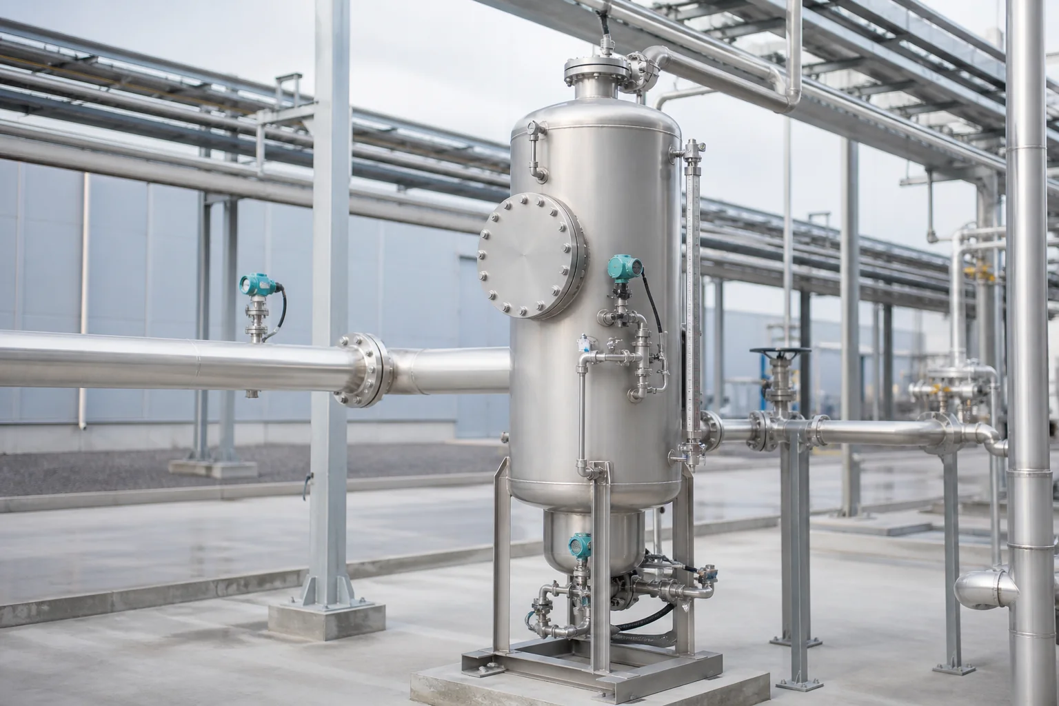
A gas-liquid separator vessel reduces gas velocity and creates space for liquid droplets to disengage. Inlet devices, demisters, liquid hold-up and level control may be added to meet the carryover target and protect downstream compressors, vacuum equipment, heat exchangers or process lines.
Separator size is driven by gas density, liquid density, flow range, droplet distribution, pressure, foaming and allowable carryover. A generic diameter cannot establish separation performance.
Vessentra coordinates geometry with the inlet device, demister, gas outlet, liquid boot, level instruments, drains, relief connection and maintenance access.
Typical applications
Application details are reviewed before equipment configuration is finalised.
Engineering configuration
The equipment is developed from process inputs, operating conditions, cleaning requirements and site interfaces.
Gas and liquid properties, flow range, droplet loading, pressure, temperature and allowable carryover define sizing.
Tangential inlet, diverter, vane pack, mesh pad or other internals follow efficiency, fouling and pressure-drop limits.
Collection volume, level range, boot, drain, pump-out and high-level protection follow the process response time.
Manways, removable internals, lifting clearances, drains and inspection points are arranged for safe service.
Specification guidance
Project limits are confirmed through engineering review. These fields describe the decisions needed for an accurate, application-specific configuration.
| Continuous phase | Gas or vapor properties defined at design case |
|---|---|
| Dispersed phase | Liquid properties and droplet target defined |
| Flow range | Normal, minimum and peak gas and liquid loads |
| Design conditions | Project-defined pressure, temperature and vacuum |
| Internals | Inlet device and demister selected by duty |
| Liquid hold-up | Level range and response time by process basis |
| Product-contact material | Stainless steel or service-compatible alloy |
| Orientation | Vertical or horizontal by separation and layout |
Common questions
It slows and redirects gas so droplets disengage by gravity and, when needed, pass through a demister before gas exits.
Provide gas and liquid flows, pressure, temperature, densities, viscosities, surface tension, droplet target, allowable carryover, foaming and fouling.
A demister is considered when gravity alone cannot meet the carryover target. Selection depends on droplets, velocity, pressure drop and fouling.
Vertical vessels often suit lower liquid loads and compact footprints; horizontal vessels can provide more hold-up. The complete duty decides.
Talk to engineering
Share the product, working volume, operating conditions, cleaning method and project location. We will use them to structure the next engineering conversation.