Dynamic sizing
Usable volume is calculated from inflow, outflow, disturbance duration, level limits and allowable pressure variation.

Stable flow between process steps
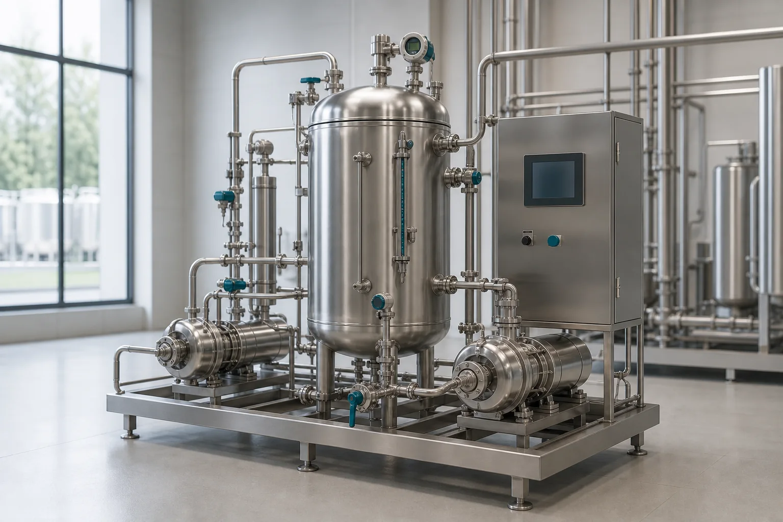
A compact pressurised buffer vessel used to decouple equipment, stabilise flow and provide controlled process hold-up.
Quick answer
A stainless steel pressure buffer tank adds controlled hold-up between process steps. It can dampen short-term flow variation, reduce pump cycling, separate batch and continuous equipment, or maintain a stable feed condition when correctly sized and controlled.
Useful buffer volume depends on the actual disturbance: pump behaviour, upstream batch discharge, downstream demand, control-valve response or gas compression. Oversizing may increase residence time and cleaning burden.
Vessentra sizes the vessel together with level range, gas space, pump duty, minimum retention, inlet momentum, outlet requirements and skid controls.
Typical applications
Application details are reviewed before equipment configuration is finalised.
Engineering configuration
The equipment is developed from process inputs, operating conditions, cleaning requirements and site interfaces.
Usable volume is calculated from inflow, outflow, disturbance duration, level limits and allowable pressure variation.
Inlet, outlet, gas space and momentum control are coordinated to avoid entrainment, vortexing and unstable response.
Level, pressure, alarms, control valves and pump interlocks are selected from the operating philosophy.
Vessel supports, pumps, valves, piping, drains, access and control enclosure are developed as one maintainable package.
Specification guidance
Project limits are confirmed through engineering review. These fields describe the decisions needed for an accurate, application-specific configuration.
| Buffer duty | Defined from process disturbance and control objective |
|---|---|
| Usable volume | Sized between agreed operating level limits |
| Design conditions | Project-defined pressure, temperature and vacuum cases |
| Product-contact material | Stainless steel selected for service |
| Gas space | Process gas or inert-gas arrangement as required |
| Instrumentation | Level, pressure, alarms and interlocks by control basis |
| Integration | Standalone vessel or complete process skid |
| Cleaning and drainage | Configured for the product and installation |
Common questions
Sizing starts with flow profiles, disturbance duration, usable level range, gas-space behavior, pressure limits and control response rather than a fixed percentage of line capacity.
No. A buffer tank is normally sized for short-term process stability, while a storage tank is sized for inventory.
The vessel can be integrated with project-selected pumps, valves, instruments, piping and a local control panel when included in the package scope.
Yes, when pressure is part of the design basis and all hygienic connections, instruments, seals and safeguards are rated for the service.
Talk to engineering
Share the product, working volume, operating conditions, cleaning method and project location. We will use them to structure the next engineering conversation.