Dynamic sizing
Inflow, outflow, cycle variation and required autonomy are modelled rather than selecting volume from batch size alone.

Stable process-line balance
A compact hygienic vessel that decouples connected process steps, stabilises flow and provides controlled short-term product holding.
Quick answer
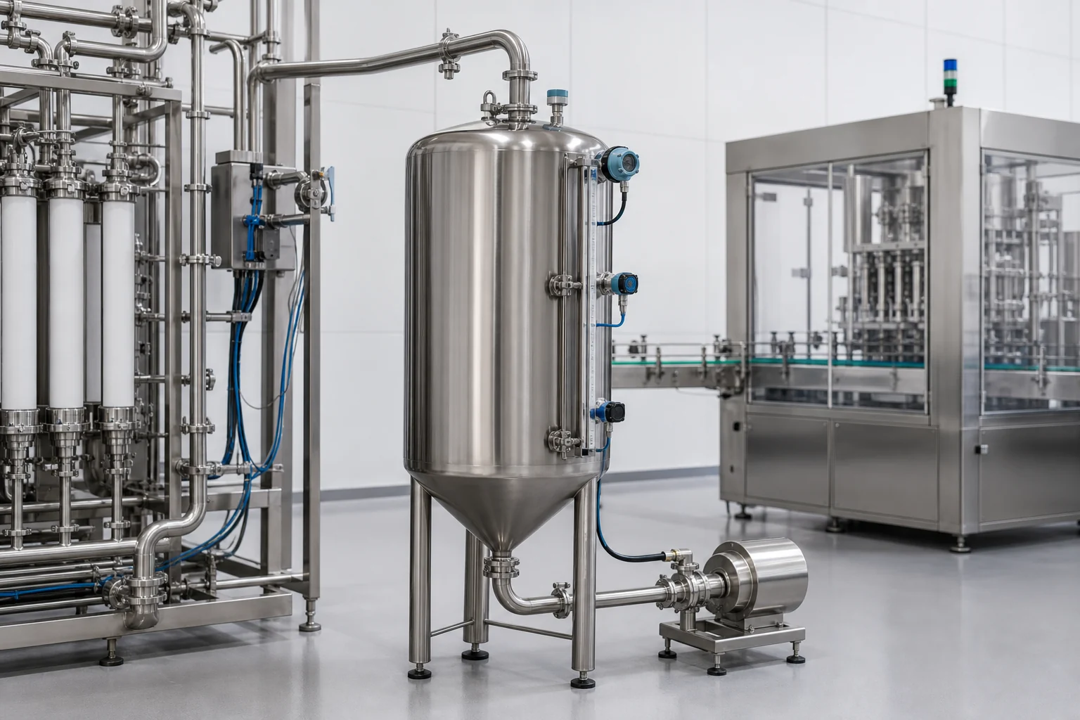
A sanitary buffer tank absorbs differences in flow or timing between upstream and downstream equipment. Correct sizing depends on production rate, cycle variation, control response, minimum working level and the amount of autonomy the line requires.
A buffer vessel is often smaller than a storage tank, but it has a more active role in line control. Poor sizing can create frequent starts, unstable levels, pump cavitation or unnecessary product residence time.
Vessentra defines the tank together with level instruments, pump control, inlet calming, outlet geometry and automation interfaces so the surrounding equipment can operate consistently.
Typical applications
Application details are reviewed before equipment configuration is finalised.
Engineering configuration
The equipment is developed from process inputs, operating conditions, cleaning requirements and site interfaces.
Inflow, outflow, cycle variation and required autonomy are modelled rather than selecting volume from batch size alone.
Point or continuous level instruments are selected around control response, foam, conductivity and product behaviour.
Inlet, outlet and minimum liquid level are coordinated to limit turbulence and provide reliable pump suction.
Signals, alarms, permissives and pump or valve control can be integrated with the line control philosophy.
Specification guidance
Project limits are confirmed through engineering review. These fields describe the decisions needed for an accurate, application-specific configuration.
| Primary duty | Flow, level or cycle balancing |
|---|---|
| Working volume | Dynamically sized from line operation |
| Product-contact material | Hygienic stainless steel selected by duty |
| Level control | Point or continuous measurement options |
| Inlet design | Configured for flow and foam behaviour |
| Outlet design | Matched to minimum level and pump requirement |
| Cleaning | Manual or CIP-ready configuration |
| Controls | Line-integration signals and logic options |
Common questions
Sizing uses the difference between incoming and outgoing flow over time, process cycle variation, minimum operating level, control response and required line autonomy.
A storage tank primarily provides holding capacity. A buffer tank actively balances connected equipment and is normally sized around process dynamics rather than long-term inventory.
It can support stable pump feed when minimum level, outlet geometry, static head and pump requirements are correctly coordinated, but the complete suction system must be reviewed.
Yes. Level signals, alarms, valve commands and pump permissives can be integrated with the agreed line control architecture.
Talk to engineering
Share the product, working volume, operating conditions, cleaning method and project location. We will use them to structure the next engineering conversation.