Fixed tubesheet
A compact configuration can be evaluated when the fluids and cleaning method suit a fixed bundle and thermal expansion remains manageable.

Process-specific thermal design
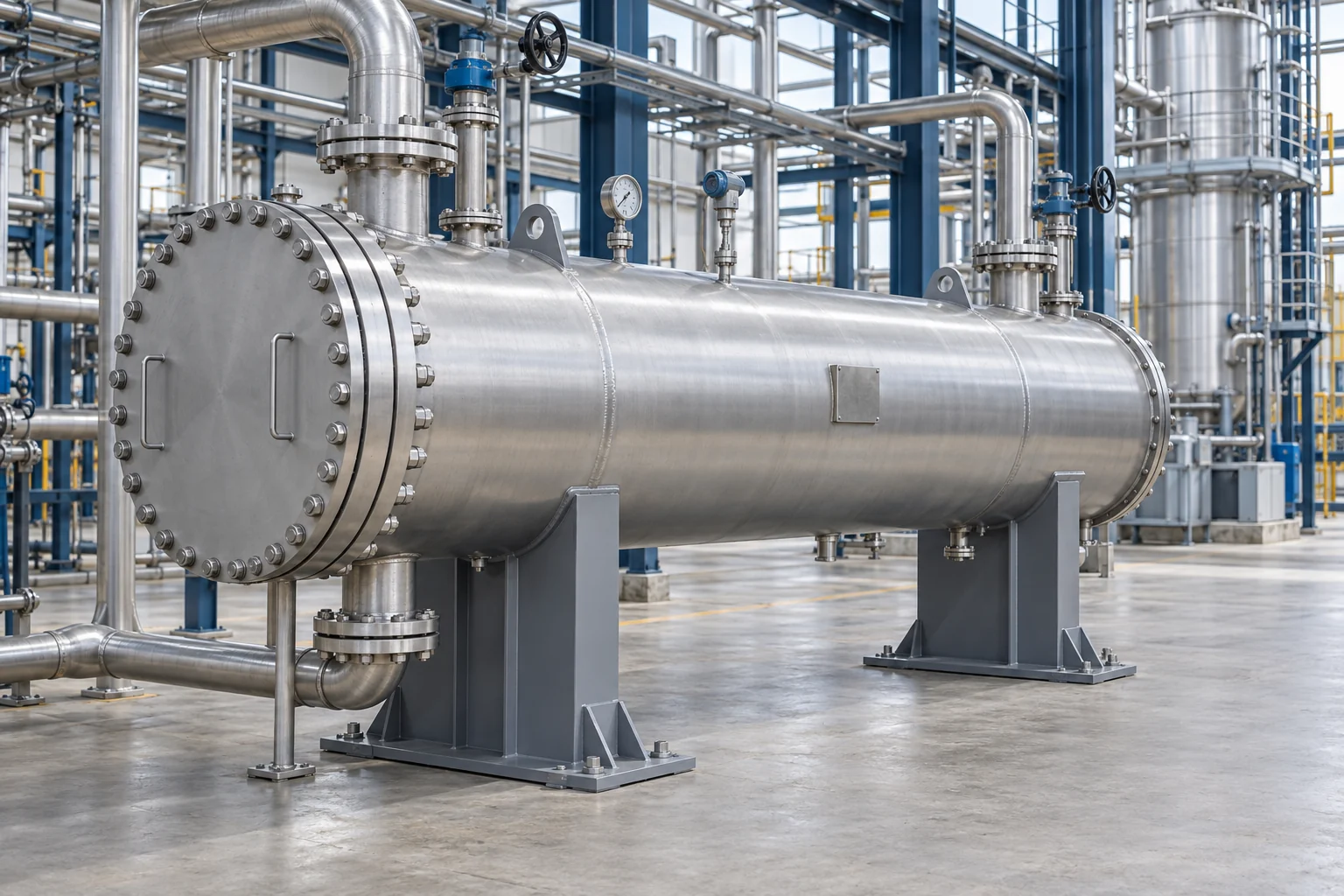
A project-engineered shell and tube exchanger that balances thermal duty, pressure drop, mechanical conditions, material compatibility and maintainability.
Quick answer
A shell and tube heat exchanger transfers heat between two separated fluid streams: one flows through a tube bundle while the other passes around the tubes inside the shell. Each unit should be sized from the actual fluid properties, flow rates, temperatures, pressure limits, allowable pressure drop, fouling risk and cleaning strategy.
Shell and tube construction is selected for duties that need a robust pressure boundary, broad material flexibility or a serviceable tube bundle. The exchanger may operate as a heater, cooler, condenser, evaporator or heat-recovery unit depending on the phase behaviour and process objective.
Vessentra develops the thermal, hydraulic and mechanical design from a confirmed process datasheet. Shell arrangement, tube pattern, pass count, baffles, expansion provision, nozzles, supports and inspection access are coordinated as one engineered system. The applicable design code and documentation scope are agreed for the installation location and project.
Typical applications
Application details are reviewed before equipment configuration is finalised.
Engineering configuration
The equipment is developed from process inputs, operating conditions, cleaning requirements and site interfaces.
A compact configuration can be evaluated when the fluids and cleaning method suit a fixed bundle and thermal expansion remains manageable.
A U-tube arrangement can accommodate differential thermal movement and allow bundle removal, subject to tube-side cleaning requirements.
A removable-bundle concept can improve shell-side access where fouling, inspection or mechanical cleaning drives the maintenance strategy.
Shell, tubes, tubesheets, baffles and gaskets are selected for corrosion, temperature, pressure, fabrication route and the agreed project standard.
Specification guidance
Project limits are confirmed through engineering review. These fields describe the decisions needed for an accurate, application-specific configuration.
| Thermal duty | Calculated from confirmed process conditions |
|---|---|
| Fluid data | Composition and properties required for both streams |
| Flow arrangement | Counter-current, co-current or project-specific pass layout |
| Exchanger configuration | Fixed tubesheet, U-tube or removable-bundle concept |
| Operating conditions | Temperature and pressure defined for shell and tube sides |
| Allowable pressure drop | Confirmed separately for both fluid circuits |
| Materials | Selected for fluid compatibility and mechanical basis |
| Documentation and testing | Specified to the destination and agreed project scope |
Common questions
Provide fluid names and compositions, flow rates, inlet and required outlet temperatures, operating and design pressures, allowable pressure drop, physical properties, fouling information, preferred materials, cleaning method and installation location.
The choice depends on differential thermal expansion, fouling location, required cleaning access, leakage risk, fluid allocation, available maintenance space and project economics.
Fluid allocation is decided from pressure, corrosion, fouling, viscosity, phase change, flow rate, cleanability and containment considerations. It should be confirmed during thermal and mechanical design.
Yes. Phase-change duties can be engineered when vapour composition, pressure, heat load, liquid distribution, condensate handling and control requirements are defined.
The applicable pressure-equipment code and any TEMA or industry requirements must be confirmed from the destination, service and purchaser specification before engineering begins.
Talk to engineering
Share the product, working volume, operating conditions, cleaning method and project location. We will use them to structure the next engineering conversation.